For the following defined terms, these definitions shall be applied, unless a different definition is given in the claims or elsewhere in this specification. All numeric values are herein assumed to be modified by the term “about,” whether or not explicitly indicated. The term “about,” in the context of numeric values, generally refers to a range of numbers that one of skill in the art would consider equivalent to the recited value (e.g., having the same function or result). In many instances, the term “about” may include numbers that are rounded to the nearest significant figure. Other uses of the term “about” (e.g., in a context other than numeric values) may be assumed to have their ordinary and customary definition(s), as understood from and consistent with the context of the specification, unless otherwise specified.
For the following defined terms, these definitions shall be applied, unless a different definition is given in the claims or elsewhere in this specification. Although some suitable dimensions, ranges, and/or values pertaining to various components, features and/or specifications are disclosed, one of skill in the art, incited by the present disclosure, would understand desired dimensions, ranges, and/or values may deviate from those expressly disclosed.
As used in this specification and the appended claims, the singular forms “a”, “an”, and “the” include plural referents unless the content clearly dictates otherwise. As used in this specification and the appended claims, the term “or” is generally employed in its sense including “and/or” unless the content clearly dictates otherwise. It is to be noted that in order to facilitate understanding, certain features of the disclosure may be described in the singular, even though those features may be plural or recurring within the disclosed embodiment(s). Each instance of the features may include and/or be encompassed by the singular disclosure(s), unless expressly stated to the contrary.
As used herein, the terms “bracket,” “housing,” and “assembly is intended to mean any material used to form an enclosure. Examples of such material include but are not limited to rigid or semi-rigid materials like plastic, metal, cardboard, and wood.
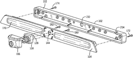
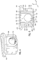
A light apparatus, system, and method will now be described with references in FIGS. 1-9. Turning to the drawings, where the reference characters indicate corresponding elements throughout the several figures, attention is first directed to FIG. 1 where a top perspective view of an embodiment of the light apparatus is shown, illustrating its composition and the apparatus is generally indicated by reference character 100. Light apparatus 100 comprises a retainer bracket 102 configured to replace a light housing, such as on a truck or trailer; a light assembly 104 connected to retainer bracket 102; and a camera housing 106 in communication with light assembly 104. A light system may comprise a retainer bracket 102 attached to a light assembly 104 and a digital or analog camera 108 retained within camera housing 106. Camera housing 106 is preferably centrally located against a top surface 170 of light assembly 104 and extends from the top edge to the bottom edge of top surface 170 but may be located against any portion of the top surface 170 of light assembly 104. Light apparatus 100 is configured to replace an existing light while also adding the capability to include a camera to view a desired region, such as being installed in the third brake light area of a truck cap or a marker light. It is contemplated light apparatus 100 may also be preinstalled on a vehicle in a location desired for a light, or in a location designed specifically for light apparatus 100.
Turning to FIG. 2, a front exploded view of an embodiment of the present invention is shown. Camera housing 106 is configured to enclose and maintain camera 108 in communication with light assembly 104. Camera 108 further comprises a plug 128 extending away from the back surface of camera 108, wherein plug 128 is configured to attach to a cord (not shown). Plug 128 extends through an aperture 144 formed therethrough light assembly 104 and may extend through an aperture 150 formed therethrough the rear surface of retainer bracket 102 and aligned with aperture 144, wherein the cord attaches to a camera viewing device (often inside the vehicle) configured to display output from camera 108 for display to a user. Aperture 144 of light assembly 104 is located in-line with plug 128 of camera 128 through the top surface 170 of the light assembly 104 and aperture 150 of retainer bracket 104 is centrally located through the rear surface of retainer bracket 104. The location of aperture 144 and aperture 150 may change to accommodate a different plug configuration of camera 108.
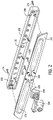
Turning to FIG. 3, a rear exploded view of an embodiment of the present invention is shown. Light assembly 104 further comprises a receiving portion 168 that is generally rectangular shaped, with a first short side 190, a second short side 192, a first long side 194, and a second long side 196, wherein short sides 190 and 192 as well as long sides 194 and 196 extend perpendicular to and away from top surface 170. Receiving portion 168 is configured to fit inside, or to be in slide into, retainer bracket 102, thereby creating a channel 172 (see FIG. 1) which allows apparatus 100 to mount to a vehicle wall, with light assembly 104 on one side of the wall and retainer bracket 102 on the other side of the wall, thereby sandwiching and securing light apparatus 100 to the wall when light assembly 104 and retainer bracket 102 are fastened together. Receiving portion 168 further comprises a first receptacle 164 on first short side 190 and a second receptacle 166 on second short side 192, wherein first receptacle 164 is configured to receive a first fastener 172 and the second receptable 166 is configured to receive a second fastener 174. Receiving bracket 102 further comprises a first passage 152 and a second passage 154, each formed therethrough the rear surface thereof. First passage 152 is located and configured in-line with first receptacle 164 and second passage 154 is located and configured in-line with second receptable 166 of receiving portion 168 of light assembly 104. First fastener 172 extends through first passage 152 and secures into first receptacle 164 and second fastener 174 extends through second passage 154 and secures into second receptacle 166, thereby attaching, or fastening, light assembly 104 to retainer bracket 102 and securing apparatus 100 to a vehicle wall. It is further contemplated light assembly 104 and retainer bracket 102 could be configured to mount to one side of a wall, such as by fasteners. In addition, light assembly 104 is configured to allow at least a portion of camera 108 to extend into or through it. Retainer bracket 102 may also be configured to allow at least a portion of camera 108 or a portion of the camera cord to extend into or through it.
Turning to FIG. 4, a front perspective view of an embodiment of camera housing 106 is shown. Camera 108 further comprises a lens 176 (see FIGS. 3 and 7). In addition, camera housing 106 further comprises an aperture 110 formed therethrough the front of camera housing 106 and is configured to allow lens 176 of camera 108 to extend through aperture 110 so that camera 108 may operate as desired. Camera housing 106 further comprises a lip 162 located around the top of camera housing 106, extending away from the front, right, and left sides of the housing and configured to keep rain and debris away from lens 176 of camera 108 which may otherwise obscure the view from camera lens. In the current embodiment lip 162 is rounded, but it may be any desired shape which performs the same stated purpose. Camera housing 106 is preferably opaque in order to reduce or eliminate glare or lens flare occurring in the viewable image produced by camera 108 caused by illumination of light assembly 104 by a LED, or other lighting method (described below).
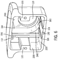
Turning to FIGS. 5 and 6, a rear view of an embodiment of camera housing 106 and a rear perspective view of an embodiment of camera housing 106 is shown. Camera housing 106 further comprises a first receptacle 122 located on a left interior wall 200 of housing 106, wherein the first receptacle 122 comprises a first cavity 126 configured to receive a first housing fastener 180. Camera housing 106 may further comprise a second receptacle 120 located on a right interior wall 210 of housing 106, wherein the second receptacle comprises a second cavity 124 configured to receive a second housing fastener 182. The location of first receptacle 122 is offset from the location of second receptacle 124 in order to ensure camera housing 106 is secured to light assembly 104 in just one possible orientation (and not accidentally upside down). Camera housing 106 further comprises a first standoff 112 and a second standoff 114 located on a top interior wall 230 of camera housing 106. Camera housing 106 further comprises a third standoff 116 and a fourth standoff 118 located on a bottom interior wall 220 of camera housing 106. First standoff 112 is in-line with third standoff 116, and second standoff 114 is in-line with fourth standoff 118. First standoff 112, second standoff 114, third standoff 116 and fourth standoff 118 as well as first receptacle 112 and second receptacle 124 are configured to be in communication with camera 108, thereby stabilizing camera 108 within camera housing 106 along the X-axis and Y-axis. It is contemplated first standoff 112 and second standoff 114 may be combined into a single standoff. Likewise, third standoff 116 and fourth standoff 118 may also be combined into a single standoff. Camera housing 106 further comprises a first slat 156 in communication with first receptacle 122 and a second slat 158 in communication with second receptacle 120, wherein first slat 156 and second slat 158 extend vertically along a front interior wall 240 of housing 106 and extend from top interior surface 230 to bottom interior surface 220 on either side of aperture 110 and are configured to stabilize camera 108 along the Z-axis. Camera housing 106 further comprises a semi-circular portion 160 extending from interior front wall 240 to aperture 110 and configured to surround lens 176 of camera 108. While first receptacle 122 and second receptacle 120 are generally rectangular in a first shape and dimensions, such as for example, about 0.2″×0.6″×0.5″; first standoff 112, second standoff 114, third standoff 116, and fourth standoff 118 are generally rectangular of a second shape and dimensions, such as for example, about 0.1″×0.1″×0.9″; and first slat 156 and second slat 158 are generally rectangular of a third shape and dimensions, such as for example, about 0.1″×1″×0.1,″ each group of elements may be varied in shape as desired to retain a particular camera within camera housing 106. Last, camera housing 106 further comprises cutout 130 extending through the bottom interior wall 220 and configured to allow liquid drainage to prevent potential damage to camera 108 caused by inclement weather.
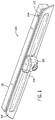
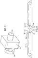
Turning briefly to FIG. 7, a rear perspective view of an embodiment of camera 108 is shown. While camera 108 currently has lens 176, plug 128, and the configuration shown which is also known as GM® part #84929557 and sold with GM® brand trucks since 2019, it is contemplated different embodiments of cameras and camera housings may be configured to hold and secure each camera type to a single light assembly 104, which allows the same light assembly to be utilized with a variety of camera types.
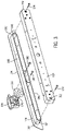
Turning to FIG. 8, a front view of an embodiment of light assembly 104 is shown. Light assembly 104 further comprises a first orifice 132 formed therethrough and located on one side of aperture 144 and a second orifice 134 formed therethrough and located on a second side of aperture 144. First orifice 132 and second orifice 134 and offset from one another, wherein first orifice 132 lines up with second cavity 124 of camera housing 106 so second housing fastener 182 (see FIG. 3) can extend through first orifice 132 and secure into second cavity 124, thereby securing camera housing 106 to light assembly 104. Likewise, second orifice 134 lines up with first cavity 122 of camera housing 106 so first housing fastener 180 (see FIG. 3) can extend through second orifice 134 and secure into first cavity 122 of camera housing 106, thereby further securing camera housing 106 to light assembly 104. To assist in aligning camera housing 106 and light assembly 104, light assembly 104 further comprises a first protrusion 136, located on and extending away from the top surface 170 of light assembly 104. First protrusion 136 further comprises a first side 250 and a second side 252, wherein the first side 250 is perpendicular to the second side 252 in a “V” shape. First side 250 of first protrusion 136 is configured to be physical communication with a first interior wall of camera housing 106 (top interior wall 230 in this case) and second side 252 of first protrusion 136 is configured to be in physical communication with a second interior wall of camera housing 106 (right interior wall 210 in this case) that is adjacent to the first interior wall, which also causes plug 128 of camera 108 to align with aperture 144 of light assembly 104. To further assist in the efficient and proper alignment of camera housing 106 and light assembly 104, a second protrusion 138, third protrusion 142, and fourth protrusion 140 may be utilized, wherein all have the same shape as first protrusion 136 but are oriented in 90 degree variations to each other and located around aperture 144 so that second protrusion 138 is in physical communication with with top interior wall 230 and left interior wall 200, third protrusion 142 is in physical communication with left interior wall 200 and bottom interior wall 220, and fourth protrusion 130 is in physical communication with right interior wall 210 and bottom interior wall 220. That is, first, second, third and fourth protrusions 136, 138, 142, and 140 are located along the interior perimeter of camera housing 106. Fasteners 180, 182, 127 and 174 may be varied in size and may comprise screws, bolts, push-fittings, or other known securing types. Further, while camera housing 106 is secured to light assembly 104 in a fixed position, it is contemplated camera housing 106 could be configured to be movable or rotatable about at least one axis so the viewing angle of camera 108 may be altered as desired by the user, such as by configuring right interior wall 210 and left interior wall 200 to each pivot, thereby rotating camera 108.
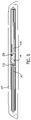
Turning to FIG. 9, a rear view of an embodiment of light assembly 104 is shown. Receiving portion 168 of light assembly 104 further comprises at least one illumination cavity 146, but preferably includes a second illumination cavity 148, each which includes a light, such as a LED light (not shown), or strip of lights, affixed within each cavity, generally to at least one cavity surface. Power for each light may attach to each light by a cable extending through a notch 254 located in retainer bracket 102 (see FIG. 1) and attached to a power source, such as a vehicle battery. Light apparatus 100 is configured so camera 108 may operate effectively, without glare or lens flare regardless of LED/light illumination or not within light assembly 104.
A light apparatus 100 may be attached to a vehicle by first enclosing a digital or analog camera 108 with a lens 176 within a camera housing 106 with an aperture 110 formed therethrough for the lens 176 of camera 108 to extent through, then connecting the camera housing 106 to a light assembly 104, and finally attaching the light assembly 104 to a retainer bracket 102, wherein the light assembly 104 and retainer bracket 102 sandwich and secure to a wall of a vehicle.
While the present invention has been described above in terms of specific embodiments, it is to be understood that the invention is not limited to these disclosed embodiments. Many modifications and other embodiments of the invention will come to mind of those skilled in the art to which this invention pertain, and which are intended to be and are covered by both this disclosure and the appended claims. It is indeed intended that the scope of the invention should be determined by proper interpretation and construction of the appended claims and their legal equivalents, as understood by those of skill in the art relying upon the disclosure in this specification and the attached drawings. Likewise, where this document refers to technologies that would be apparent or known to one of ordinary skill in the art, such technologies encompass those apparent or known to the skilled artisan now or at any time in the future.