If the articulating running boards (tri-mode) on your late model GM truck are not working properly you are not alone.
- It’s common for the running boards to partially extend, only to immediately retract again.
- You may also notice that the kick switches at the end of the running board don’t work either.
- In some other cases the running boards take on a mind of their own and start extending and retracting without any user intervention, even with the truck completely powered down and no one near it.
- The running boards may even not work at all when the doors are opened.
It just so happens that our shop truck had all of these issues, so we are going to address everything previously stated. If all your switches still work, you may only need to address the partial opening. The good news is that repairing the running boards is not too difficult and can be done by someone with average mechanical skills for less than $500. We will cover the common components and show you how to address all the issues previously mentioned, and you’ll have your running boards back to working like new again in no time.
What Causes Articulating Running Boards to Stop Working?
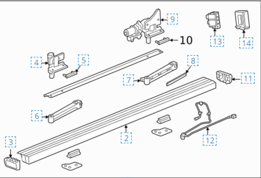
The main reason that the boards only partially extend is because the bushings corrode over time and the motors are not able to overcome the force needed to work the bushing past the corrosion resistance. You can see from the image that the board’s mechanical function comes from two extension arms on each side of the truck (part 6 and 7 , total of 4 arms, front and rear on both sides).
The rear extension arm is attached to the drive motor (item 9) that does all the work in terms of extending and retracting. The drive motor side of the extension arm slides onto the motor shaft then is pinched tight using two allen head screws. The front extension arm is attached to a frame mounted shaft (item 4) in a similar fashion, which has sealed bearings inside that allow the board to move in and out.
The running board end of all the extension arms have two stainless bushings that ride inside of two plastic bushings that are pressed into the hole at the end of the arm. There are rubber seals at the top and bottom that are supposed to prevent moisture from getting into the bushings but over time it’s inevitable that some moisture will penetrate, which is where the problem begins. After enough moisture and time the bushings eventually seize up and the motor cannot overcome the resistance it causes.
How To Repair Articulating Running Boards
In the case of our shop truck we are also going to replace item 11 (84266750 switch and 84266749 switch) as well as item 13 (84835967 control module). Again our truck had the “ghost boards” where they would just start moving in and out without any user intervention, so we attributed that to the control module.
1. To begin the repair, pull the fuse (located in the engine compartment fuse box) for the running boards or disconnect the negative terminal on the battery.
2. Next get the truck in the air if you can as it will make your life a lot easier. We are going to start working on the rear extension arm on the driver’s side first, which is the one connected to the motor.
3. Start by loosening the two allen head screws that are clamping the extension arm to the motor shaft. No need to remove them all the way, just loosen them so the arm can eventually slide off the shaft.
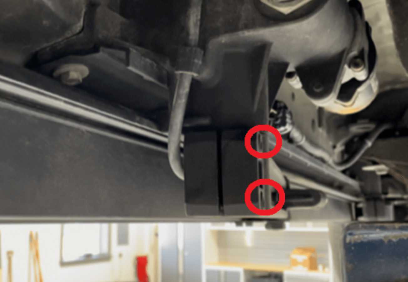
4. Next, work on removing the hardware that is securing the front of the arm to the running board. For this step you’ll need a 10mm socket and a 1” socket for removing the mounting bracket. The small metal bracket will be removed once the two 10mm and the 1” nut are removed completely.
Don’t worry about the arm falling off just yet because it’s probably corroded and stuck but we do suggest getting a support stand under the board to prepare for the next step of removing the extension arm from the vehicle.
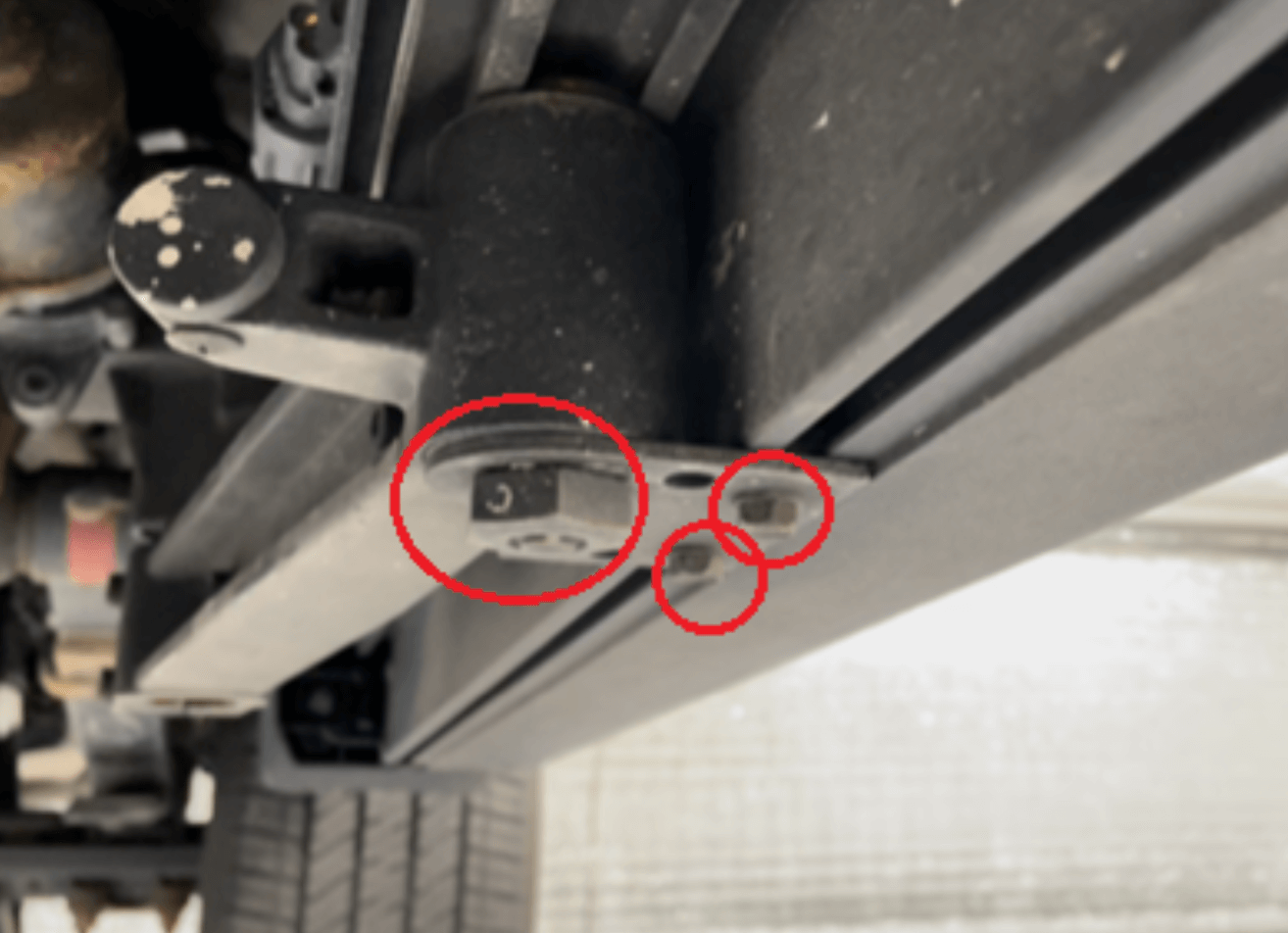
5. Now that everything is loose, you’ll be ready to remove the arm by gently (or maybe not so gently) prying the arm downward at the ends. Again, having something under the board to support it is essential because the running board will fall without any support.
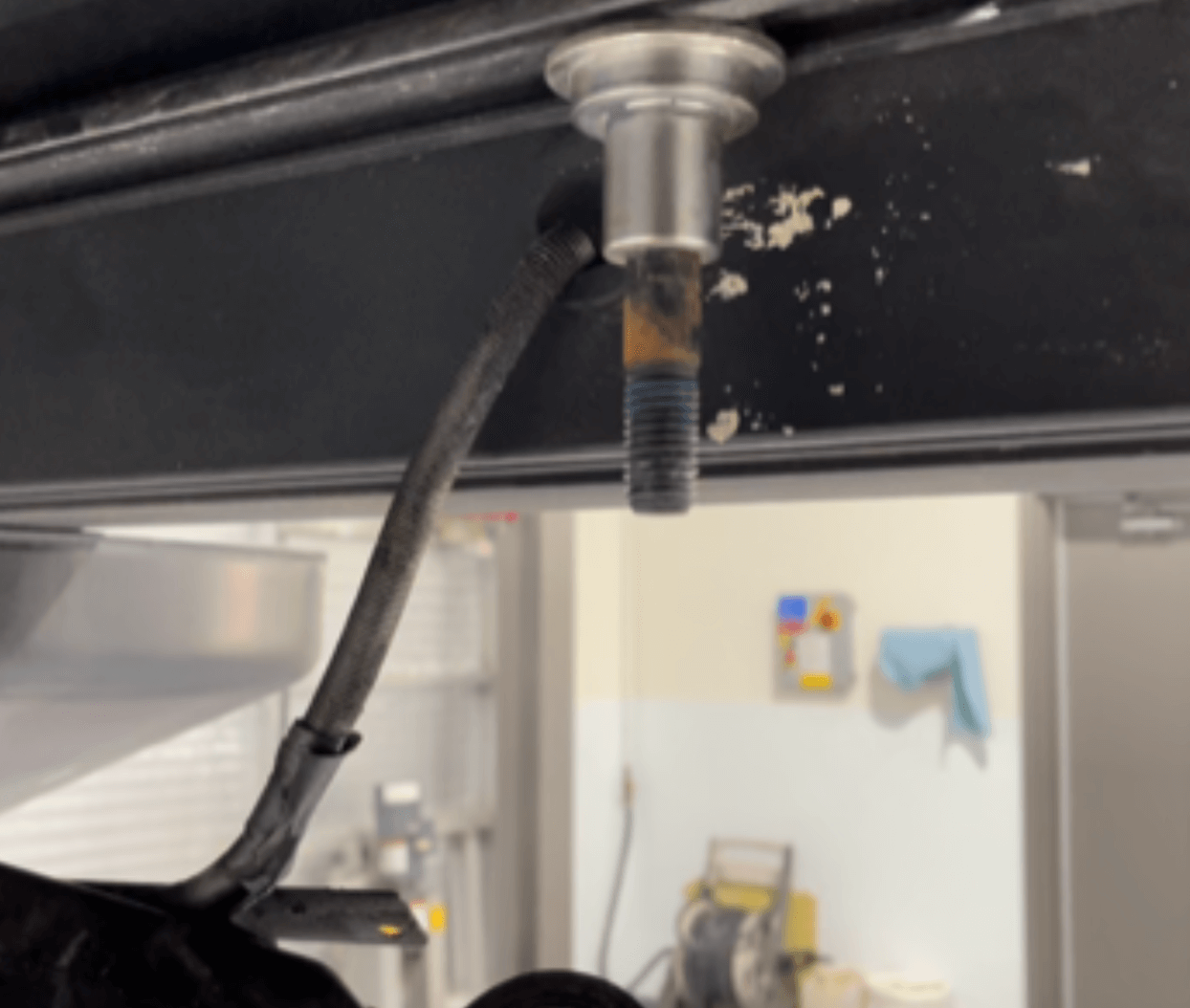
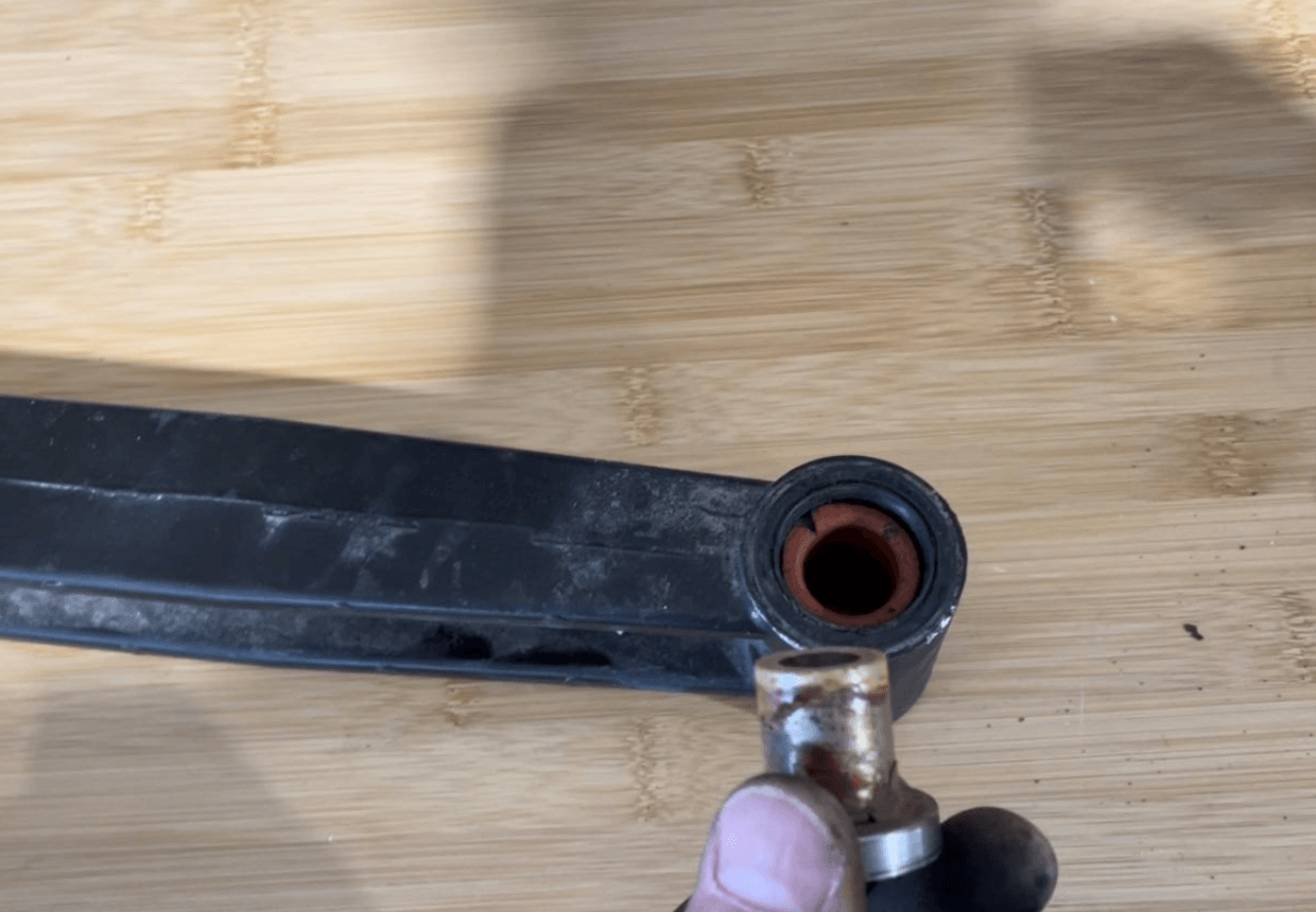
6. Once the extension arm is removed you can remove the stainless bushing from the bottom of the front mount point and get it cleaned up.
Chances are it’s completely corroded like it was on our truck. A simple wire brush should do the trick and don’t forget to use some cleaner on the inside of the arm mount where the plastic bushings are pressed in.
7. You will also need to clean the mounting bolt that is on the running board; clean the bushing and the bolt completely as you will likely see some rust on the bolt as well (see photos).
8. Once the bushings, inserts, and bolt are completely clean, coat them with some anti-seize grease to ensure you’re not back at this again in six months.
9. You’ll also want to check the integrity of the rubber seal at the top and bottom of the bushing inserts on the extension arm to ensure it’s still soft and not damaged.
10. Put a small amount of grease around the bushings as well.
11. Prior to putting the arm back on, take a little time to clean the motor shaft and put a thin coating of grease on that as well, so that reassembly is a little smoother. If the seals or bushings are actually damaged you’ll need to buy a new control arm since they don’t sell them separately.
12. With the bushings back in the extension arm start the reassembly process ensuring the arm is oriented the same way it was removed. You’ll have to get both sides of the arm started together and press up on them evenly as you slide the extension arm back into place.
NOTE: There is a plastic washer that goes on top of the arm on the motor side so don’t forget to put that on first.
13. Ensure the arm is slid all the way to the top of the mounting bolt on the board so that the seal is seated properly into the bushing before tightening the nut and mounting bracket again.
14. You can snug the allen screws on the motor shaft but do not tighten them yet because leaving it slightly loose will allow you to manually slide the board in and out as you work on this project.
15. You will tighten the allen screws after everything is done and the board is back in the fully retracted position. You can, however, tighten the 1” and 10mm screws on the front bracket completely.
16. The front extension arm will be done in nearly the identical steps but you will need to check freedom of movement on the frame mounted shaft (where the rear of the extension arm mounts to, item 4 in the part diagram). This shaft needs to move freely and it too is likely corroded and will either need to be replaced or lubed.
We were able to remove and lube ours by flipping it upside down, injecting penetrating oil past the seal and working it back and forth multiple times, but replacement is probably a better option. Each side has a different part number and they run about $110 each at the time we wrote this article. We figured we could always replace it later if it fails again so we opted to lube it!
17. You will repair both the drivers side and passenger side steps the same way and then you’re ready to replace the switches and controller.
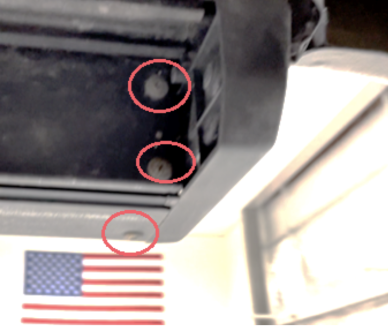
18. There are three self tapping screws that hold the switch into the end of the running board. Simply remove the three screws and it will pop right out with a little love tap.
19. Once removed, you’ll see the wire connector which has a small red lock tab that will have to be released before you will be able to press down on the connector release button.
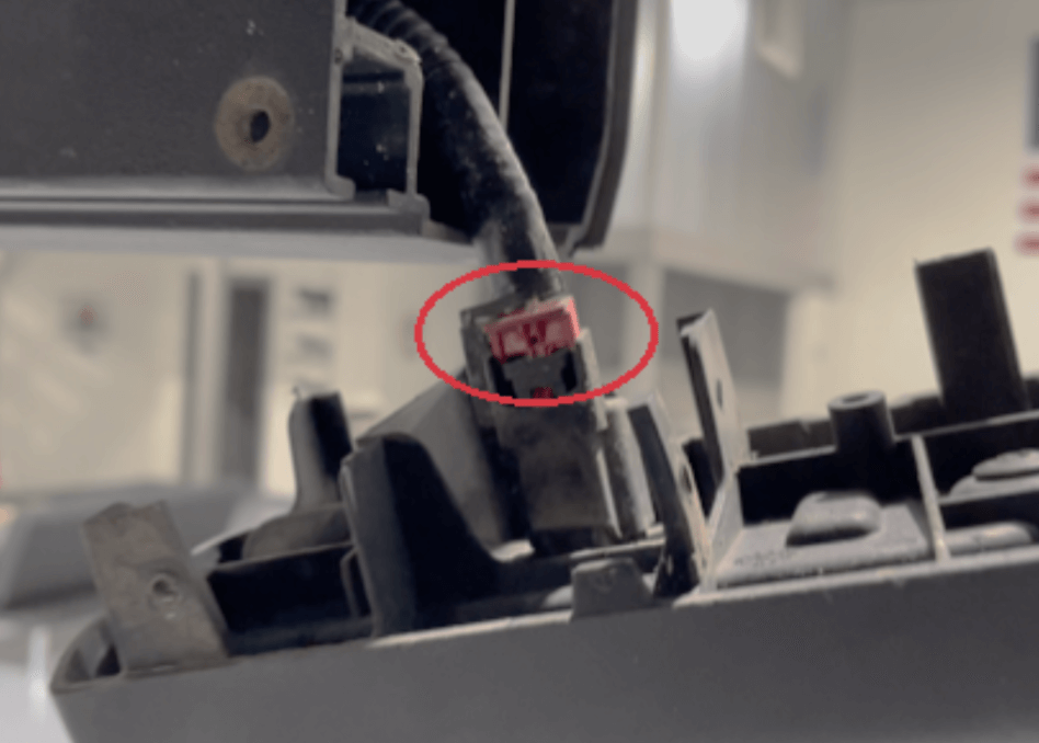
20. Use a small flat head screwdriver to pop the release away from the seated position as shown in the picture.
21. Replacing the switch is easy, so just put it back together the same way it came apart, but don’t forget to slide the red lock back into position when everything is connected again.
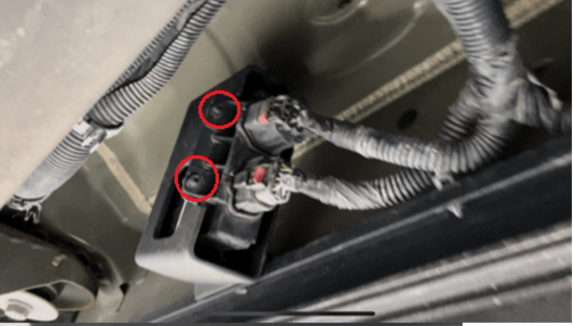
22. Next we replaced the control module, which is located on the passenger side along the frame rail. There are two wire connectors inserted into it and there are two T-25 torx head screws holding the module into the frame mount.
23. Be careful when removing the torx screws as they typically are corroded and will break off. The wire connectors have a similar style red locking tab that will need to be released before the connectors can be removed so don’t break them off!
24. After everything is reassembled ensure the boards are pushed back in all the way to the fully retract mode and then tighten the allen screws on the motor and frame shaft.
25. When complete you can lower the truck back down and reconnect the negative terminal on the battery to get the juice flowing again.
Check Your Work
If your truck is like ours, you will notice that when you open the door it will surprise you by doing absolutely nothing at all. This wasn’t a great feeling since we were expecting the step to pop right out the second we opened the door! No big deal. As it turns out, when the battery was disconnected, our boards went into disabled mode, so we had to hold the power button down inside the cab for 10 seconds and then they came alive once again.
The entire process took about 2 hours and cost about $425 in parts. This is unquestionably a dirty job so be prepared to get messy and don’t expect those control arms to come off easy. Years of corrosion is holding those extension arms onto the shaft and bushings - but with some elbow grease and a hammer they will eventually pop off!
Questions, comments, concerns? Get in touch with us and tell us how we can help, or let us know how we’re doing. You can also browse our helpful blog for more resources, or start browsing our inventory for backup cameras to enhance your safety.

